| Transducer |
Industrial and municipal wastewater must be treated to the specified standards before discharged into a sewer or watercourse. These standards are determined not only to protect the sewerage infrastructure and workers maintaining the sewerage system, but also to prevent adverse effects on treatment processes at the downstream sewage treatment works and protect aquatic life. As water pollution acts become more and more strict, it is important to monitor multiple parameters of effluent conveniently during the treatment and before discharge. Therefore, it is necessary to develop an instrument to measure these parameters conveniently and efficiently.
Current available instrumentations are capable of measuring pH value of aqueous solutions, oxidation/reduction potential (ORP), free ion concentrations of some anions and metallic ions, conductivity, the concentration of dissolved oxygen (DO) and temperature. However, only a common instrument can measure some of these parameters among the standards of environmental pollution control acts at present. It is inconvenient to measure all parameters of effluent by many separate instruments, and hence it is important to develop one integrated instrument for more parameters. Many electrochemical measurements are affected by environmental temperature, and the results should be corrected to compensate the effect of temperature after measurement. In fact, some of electrochemical sensors have temperature compensation functions and they are duplicated if the functions are integrated instrument for more parameters. In addition, most of conventional electrochemical instruments are composed of the same components, such as liquid crystal display (LCD), keypad, and digital output port. It is necessary to integrate these similar or same functional parts into a system and save the cost.
We designed and fabricated an integrated transducer to determine multiple parameters, which include pH, oxidation/reduction potential, temperature, conductivity, dissolved oxygen, the concentrations of some of anions and metallic ions. The transducer is composed of multiple input ports for standard commercial sensors, microprocessor for energetic data treatment, liquid crystal display for easily operation and directly result representation, keypad for input and digital output port for communication with personal computer. The transducer provides powerful functions, including flexible calibration strategy, optimized display mode, intelligent internal compensation, and wide measurement range.
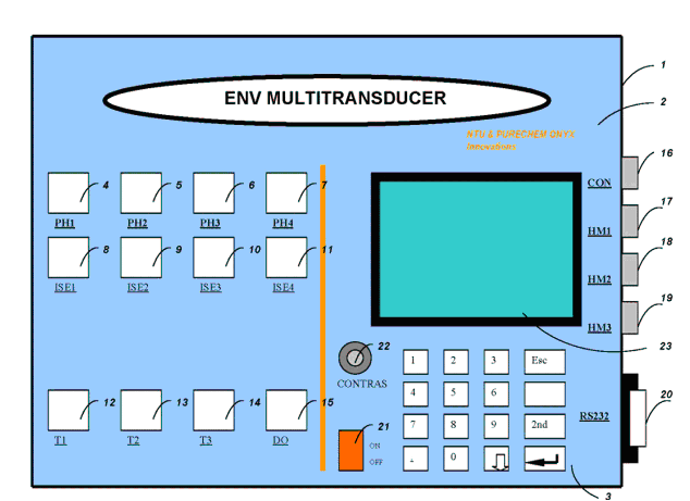
Fig below illustrates the front
of an integrated transducer 1 for environmental multi-parameter monitoring
according to one embodiment of the present invention. The case 2 of the transducer
covers the exterior of the meter except for a panel containing the keypad
3, liquid crystal display 23, a series of jacks for standard commercial probes
and the accessories. The keypad includes sixteen keys, eleven of which are
number keys, and others are function keys. The transducer has eight jacks
(4 to 11) for pH, ORP and ion selective electrodes, and three jacks (12 to
14) for temperature probes, and one jack 15 for DO electrode through the top
of the case. The transducer has one jack 16 for conductivity electrode, and
three jacks (17 to 19) for the working, reference and counter electrodes of
anodic stripping voltammetry (ASV) for the monitoring of metallic ions such
as some of heavy metals through the right side of the case. The transducer
has a digital output port 20 to communicate with the computer under the protocol
of RS232 in the right side of the case, and an on/off button 21 to switch
on and off the power of the transducer in the front panel of the case, and
a contrast knob 22 to adjust the display contrast of the LCD in the front
panel of the case.

Schematic diagram of the integrated transducer
Fig.below is a schematic diagram of the functional components of the transducer. The pH or ORP or ion selective electrodes (ISE) are connected via the jacks (4 to 11) to the transducer. The analog voltage input 24 (actually 8 channels) of pH or ORP or ISE is connected to an analog amplifier circuit 25 to a strobing circuit 55. The temperature probe is connected via the jacks (12 to 14) to the transducer. The analog input 27 (actually 3 channels) of temperature probe is connected to an analog amplifier circuit 28 to a strobing circuit 55. The DO electrode is connected via the jack 15 to the transducer. The analog current input 32, which is produced by DO electrode under the polarizing voltage signal 31 of the polarizing voltage circuit 30, is connected to current to voltage circuit 33 to convert to voltage signal 34, and then the voltage signal 34 is connected to an analog amplifier circuit 35 to a strobing circuit 55. The conductivity electrode is connected via the jack 16 to the transducer. The analog current input 39, which is produced by conductivity electrode under the alternating voltage 38 of the oscillation generator circuit 37, is connected to current to voltage circuit 40 to convert to voltage signal 41, and then the voltage signal 41 is connected to an analog amplifier circuit 44 to the strobing circuit 55. The amplification gain of analog amplifier circuit 44 is controlled by the signal 43 of the controllable gain 42, which receives control signal 61 from the microprocessor 59. The working electrode, reference electrode and counter electrode of ASV to measure the concentration of metallic ions are connected via the jacks (17 to 19) to the transducer. The analog current input 48, which is produced by the electrodes under the deposition and stripping voltage 47 of the circuit 46, is connected to current to voltage circuit 49 to convert to voltage signal 50, and then the voltage signal 50 is connected to an analog amplifier circuit 53 to the strobing circuit 55.The deposition and stripping voltage circuit 46 receive control signal 63 from the microprocessor 59. The amplification gain of analog amplifier circuit 53 can be controlled by the signal 52 of the controllable gain 51, which receives control signal 62 from the microprocessor 59.

Schematic diagram of the functional components of the transducer
The voltage inputs (26, 29, 36, 45 and 54) connected to the strobing circuit 55, are transferred to A/D converter 57, which converts analog input 56 into a digital signal 58 one by one in proper order. The digital signal 58 is an input into microprocessor 59, contained on a circuit board within the case 2 of the transducer 1. Keypad input 66 represents the connection of the various keys of keypad 3 to the microprocessor 59. Output 65 from microprocessor 59 to display 23 is representative of various control lines that connect microprocessor 59 to the individual liquid crystal display elements of the components of display 23. Output 64 from microprocessor 59 is representative of various control lines that connect microprocessor 59 to the serial communication port of the computer under the communication protocol RS232.
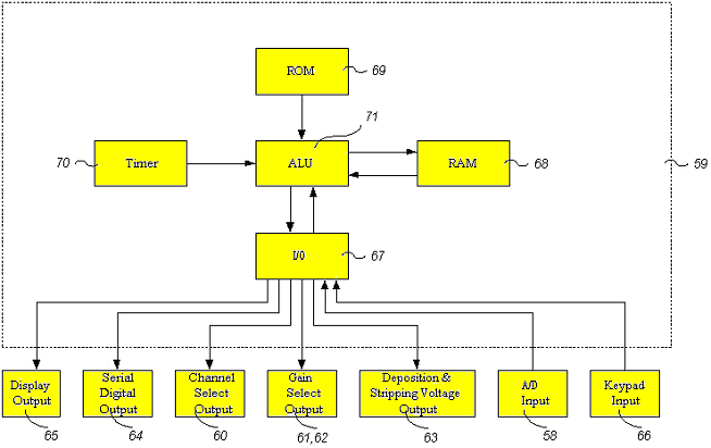
Fig below illustrates in schematic form of the microprocessor 59, its major logic elements and the connecting elements. The two types of inputs to the microprocessor 59 are the digitized input 58 (shown as coming from A/D Converter 57 in Fig. 2) and the keypad input 66 (shown as coming from keypad 3 in Fig. 2). The five types of outputs from the microprocessor 59 are the display outputs 65 to LCD 23, the serial digital output 64 to RS232 serial communication port 20, the channel selector output 60 which controls the strobing circuit 55 to determines whether A/D Converter 57 is connected to pH/ORP/ISE jacks (4 to 11) or to temperature jacks (12 to 14) or to DO jack (15) or to conductivity jack 16 or to heavy metal jacks (17 to 19), the gain select outputs (61 and 62) which control the gains of the amplifiers (44 and 53), and the deposition and stripping voltage output 63 which control the deposition and stripping voltage 46 of anodic stripping voltammetry.

Schematic form of the microprocessor 59
The two types of inputs and five types of outputs connect through the I/O interface 67 to the arithmetic logic unit (ALU) 71 of microprocessor 59. Additional inputs to ALU 71 are timer circuits 70 used for indicating increments at which ALU performs certain functions. The microprocessor 59 also contains read only memory (ROM) 69 in which various program routines and constants are permanently stored and called up by ALU in a controlled fashion. Random access memory (RAM) 68 contains various values obtained by ALU 71 from I/O 67 or from computations on those values, on stored values already in RAM 68, on values from ROM 69 or on values from a variety of sources.
The integrated electrochemical transducer can measure the multiple parameters of the solution, such as pH, ORP, temperature, conductivity, DO, concentration of some anions and metallic ions. When the transducer is turned on, all the parameters will display in the LCD, and the operator press the key to select the parameters to be measured.


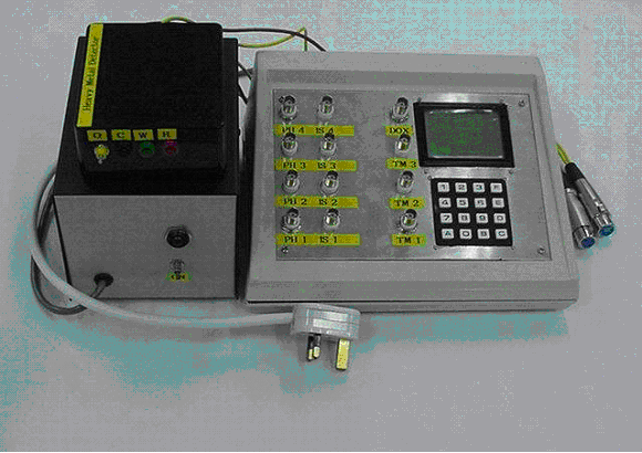
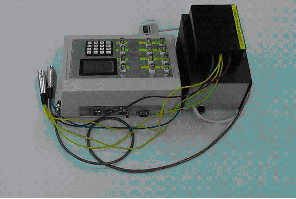
The front view and reae view of the integrated
transducer integrated with power supply and accessories