
IRIS Primary Payload
The IRIS system consists of two units, Electro-Optical Unit (EOU) and Processing and Control Unit (PCU). Figure 1. shows the simplified preliminary system block diagram.
EOU consists of the Telescope and the Focal Plane Assembly (FPA). The Telescope is made of various optical and structural components. FPA houses three linear detectors and the front-end electronics (FEE). Within FEE, low-level video signal conditioning and clock pulse generation are performed. Within EOU, there are two survival heaters for Telescope and FPA. These heaters are under direct control of the spacecraft bus.
PCU consists of four electronics modules in a single mechanical box. The Power Supply Module (PSM) generates electrical power supplies for other modules from the unregulated bus power of +24 ~ 32 V. The Signal Processing Module (SPM) processes and digitizes video signals and transmits the digital image data to the Control Module (CM). As the heart of the IRIS system, CM performs the management of the overall system through a serial communication link with the command and data handling subsystem of the spacecraft bus. It also performs the maintenance of the stored image data. It can transmit either quick-look image data or stored image data through the transmission subsystem of the bus in high speed.
Figure 1 Preliminary System Block Diagram of IRIS
The preliminary specifications of the IRIS system are listed in the following table: These figures are subject to change as the development progresses and in accordance with the development of interfaces with the spacecraft bus.
| Item | Specification | Remarks |
|---|---|---|
| Spectral bands | 0.52 ~ 0.60, 0.63 ~ 0.69, 0.76 ~ 0.89mm | Nominal |
| Ground sample distance (GSD) | 10m | @ 685 km & nadir |
| Swath width | ³ 50km | @ 685 km & nadir |
| Modulation transfer function (MTF) | ³ 15% | @ pixel Nyquist frequency for all bands |
| Signal-to-noise ratio (SNR) | ³ 100 | For ρ = 0.25, θz = 60 ° |
| Signal Quantization | 10 bits | 8 bits used |
| Signal Gain | Programmable | |
| Data Storage capacity | 8 Gbits | @beginning of life |
| Power Consumption | <25 W | Peak Value |
| Dimensions (mm) | EOU: f180 ´ 530 PCU: 320 X 210 X 150 |
|
| Mass | < 12 kg | Total Value |
| Data Transmission | TBD |
Table: Preliminary Specification of IRIS in normal operation mode
The preliminary hardware component breakdown structure for IRIS is shown below:
Figure 2 Preliminary System H/W Configuration
The key features of EOU and PCU are shown in below tables:
| EOU | Feature | Remarks |
|---|---|---|
| Spectral Bands | 0.52 ~ 0.60, 0.63~0.69, 0.76 ~ 0.89mm | Nominal |
| Pixel Pitch | 7mm | |
| Active pixels | ³ 5,000 | Per Band |
| IFOV | 14.6 mrad | |
| Aperture | 120 mm | Diameter |
| FOV | 4.6 ° | |
| EFL | 480 mm | |
| F-Number | 4 | |
| Distortion | 0.5% | |
| Band Registration | < 0.5 pixel | |
| Obscuration | 0.25 | Area |
| MTF | 44% : Optical Design 55%: FPA 15%: System |
@ 71.4 cycles/mm |
| SNR | ³ 100 | For ρ = 0.25, θz = 60 ° |
| O/P Data Rate | ³3.4M pixel per second | Analog per band |
| Natural Frequency | ³ 100 Hz | |
| Dimension (mm) | < f180 ´ 530 | |
| Mass | <7.3 kg |
| PCU | Feature | Remarks |
|---|---|---|
| Signal Gain | Programmable | |
| Offset Correction | Automatic + Programmable | |
| Input Voltage | +24 ~ 32 V | Regulated or Unregulated |
| Power Consumption | <25W | Including FPA |
| I/P Data Rate | ³ 3.4M pixel per second | Analog per band |
| I/P Data I/F | 3 coaxial cables | |
| Micro-processor | TSPC68360 | |
| Bus Communication | UART Serial Link | |
| FPGA | Radiation-tolerant ACTEL Series | |
| Storage capacity | 8 Gbits | @ Beginning of life |
| Quick-look data | Supported | |
| O/P Data Rate | 30 Mbps | Baseline (TBD) |
| O/P Data I/F | I, Q, Clock | Baseline, TTL for QPSK |
| Natural Frequency | ³ 100 Hz | |
| Dimension (mm) | < 320 X 210 X 150 | |
| Mass | < 4.5kg |
Summary (as at April 06)
The IRIS modules (EOU and PCU) has been subjected to thermal tests and random vibration tests in Dec 05, and its preliminary findings were that the EOU can withstand the anticipated launch environment although its optical performance (MTF) was found to be below specifications. The EOU would be re-manufactured and the entire modules are scheduled to be delivered by Jun06.
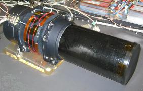
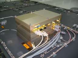
The above pictures show the EM/QM EOU (Left) and PCU (Right).