Steering Committee Organization Team Members Schedule
Space Segment Ground Segment Launch Segment
Space Segment
(a) Bus:
(b) Payload:

XSAT Power Supply Subsystem

The X-SAT power supply subsystem (PSS) consists of two major modules, namely the power control module (PCM) and the power distribution module (PDM). The basic architecture of the PSS uses the simple and robust direct energy transfer scheme. The solar panel uses the triple junction GaAs solar cells. It is estimated that a total of 342 cells would be used. Depending on the temperature of the solar panel, the estimated peak power is above 250W. The main bus voltage is between 16.0V to 30.5V. The required battery capacity is 13.5Ah. Table 1 summarizes the key parameters of the PSS.

Architecture Direct Energy Transfer (DET)
Solar Array Size 342 cells in 19 series 18 parallel configuration
Max. Solar Cell Efficiency, η ~27 %
Solar Cell Type Triple Junction GaAs
Peak Power Output Between ~380W@-50°C and  ~260W@+110°C
Battery Capacity 13.5Ah (340Wh)
Battery Voltage Nominal 25.2V, Maximum 29.4V
Main Bus Voltage 16.0V to 30.5V
BCR Efficiency > 90%
MBR Effiiciency > 85%

Table 1: Key parameters of the PSS

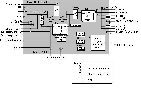
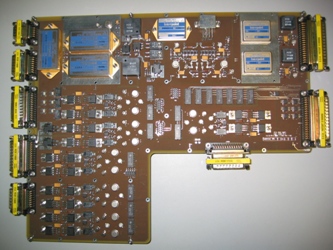
Power control module (PCM)

The function of the PCM is to regulate power transfer between the solar array, battery and the subsystems of the satellite. The PCM consists of a battery charge regulator (BCR), which is a step-down converter and main bus regulator (MBR) together with telemetry acquisition and main bus protection electronics.

a

PSS architecture

In general, the satellite’s orbit can be broken down into two phases, namely the sunlight phase and the eclipse phase. The solar array converts the sunlight into electrical energy during the sunlight phase. Moreover, it also supplies the power to the subsystem and charges the batteries through the BCR during this phase. During the eclipse phase, the batteries supply the power to the subsystem through a discharge diode. The voltage of the main bus is converted by the MBR to an unregulated 16V to 30.5V at the output of PCM. The energy transfer between the solar array, batteries and subsystems ensures that the power is available to the subsystems throughout the mission.

a
PCM

Power Control Module

As shown above, there are sensors at various points to acquire key telemetry data during the orbit, e.g.  voltages, currents and temperatures of solar panel and batteries. Protection circuit includes the low-voltage (LV) protection relays and fuses. In the event of current overload of the fused lines, the fuse wil blow to protect the main bus. The LV relay separates the other subsystems from the PCM to protect the battery from over-discharge in case the voltage level falls below a critical level. Redundancies in the critical components are also included to prevent single point failure in the subsystem. Control logic circuitries are required to activate cold redundant BCR as well as to isolate faulty hot redundant MBR.

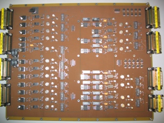
Power Distribution Module (PDM)


a

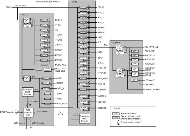
PDM Implementation Block Diagram

PDM1


PDM1

PDM2


PDM2

The main function of the PDM is to distribute power for the various subsystems. 32 switchable cum over-current protected lines and 5 non-switchable regulated lines to various subsystems. In the satellite, it physically consists of two trays – PDM-1 tray and PDM-2 tray, as well as AIM-PWR integrated into the AIM tray. PDM-1 supplies 20 unregulated 28V (16V to 30.5V) lines to various ADCS sensors and actuators, AIM, TT&C, X-Band, IRIS, SSR and PPU. PDM-2 supplies 3 regulated 5V non-switchable but fused lines to OIM, 12 regulated switchable 5V lines to OBC, GPS_A, GPS_D, IRIS, all CAN nodes as well as the domestic supply for PDM circuits. The current telemetries from PDM along with other telemetries from PCM will be input to the 8-channel multiplexers. The output will be sent to the CAN node, digitalized by ADC before being fed back to the OIM.

Each switchable cum over-current protected line contains a FET-switch, a current sensor and an over-current detection circuit. Each FET-switch is controlled by an OIM switch command as well as the over-current detection circuit. On/off status is fed back to OIM. The current sensor monitors the current level, feed back this current level to the over-current detection circuit. Once the current level exceeds a pre-set value, the over-current detection circuit will turn off the switcher.