MODELLING AND
SIMULATION OF GaAs HIGH-SPEED HBT, MESFET, AND HEMT ANALOGUE/DIGITAL CIRCUITS
Zhou Xing and Tang Tianwen
School of Electrical &
Electronic Engineering
Nanyang Technological University
Abstract
| Figures | Back
(Click on the Figure inside the Paper to see its enlargement.)
Figures
Fig. 1 | Fig. 2 | Fig.
3 | Fig. 4 | Fig. 5 | Fig.
6 | Fig. 7 | Fig. 8 | Fig.
9
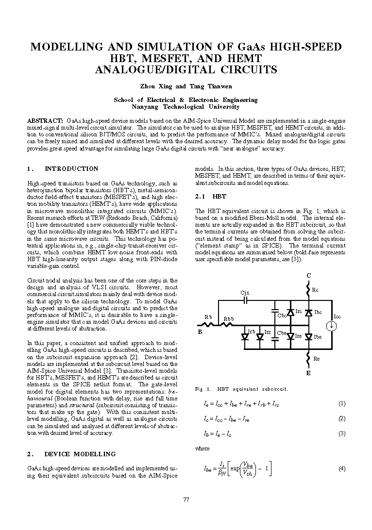
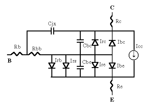 Fig. 1 HBT equivalent subcircuit.
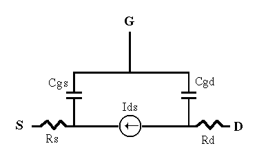 Fig. 2 MESFET equivalent subcircuit.
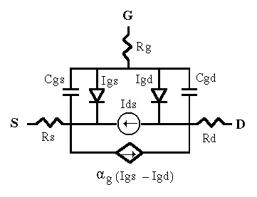 Fig. 3 HEMT equivalent subcircuit.
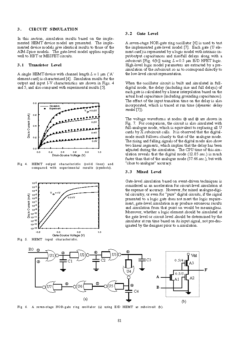
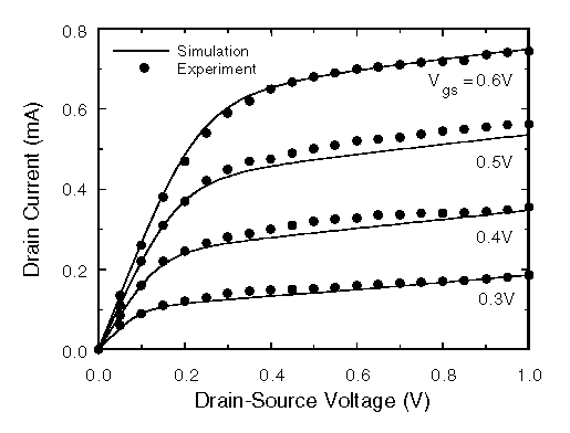 Fig. 4 HEMT output characteristic (solid lines) and compared with
experimental results (symbols).
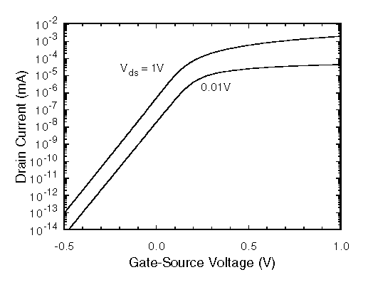 Fig. 5 HEMT input characteristic.
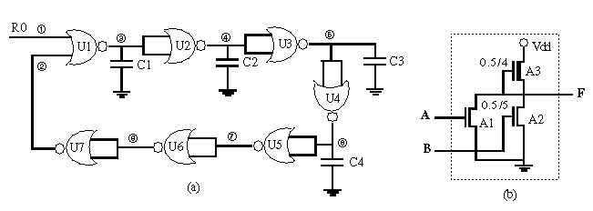 Fig. 6 A seven-stage NOR-gate ring oscillator (a) using E/D HEMT
as subcircuit (b).
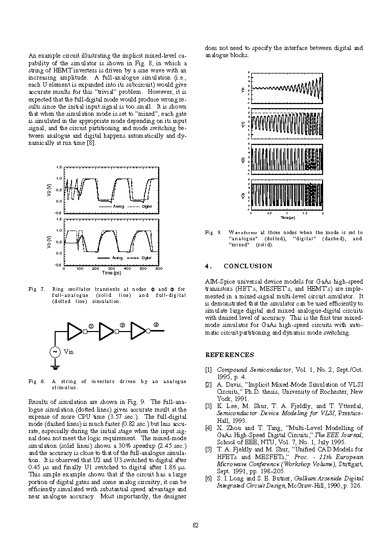
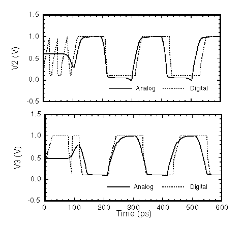 Fig. 7 Ring oscillator transients at nodes 2 and 3 for full-analogue
(solid line) and full-digital (dotted line) simulation.
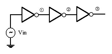 Fig. 8 A string of inverters driven by an analogue stimulus.
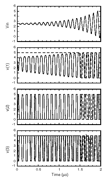 Fig. 9 Waveforms at three nodes when the mode is set to "analogue"
(dotted), "digital" (dashed), and "mixed" (solid).


