Filter banks
(1) Decimation and Interpolation
In most applications, the decimator is preceded by a lowpass digital filter called the decimation filter. The filter ensures that the signal being decimated is bandwidth limited.

Next, an interpolation filter is a digital that follows an expander. The typical purpose of the digital filter is to suppress all the images caused by the expander.
The relationships of the input-output are:

in time-domain, and

in frequency domain.
(2) Some special filters
M transfer functions Hk(z) are said to be power complementary if
![]()
A filter is said to be an Mth band filter (or Nyquist(M)) filter, if the impulse response h(n) satisfies
![]()
Above equation implies that ![]() . So we can conclude that all these
M uniformly shifted versions of Mth band filter H(ejw )
add up to a constant.
. So we can conclude that all these
M uniformly shifted versions of Mth band filter H(ejw )
add up to a constant.
(3) Noble Identities
We can interchange the positions of interpolator (decimator) and filters with the noble identities

(4) Polyphase Decomposition
An important advancement in multirate signal processing is the invention of the polyphase representation of a filter:
![]()
The impulse response of the kth polyphase filter Gk(z) is simply a subsampling of h(n+k):
![]()
This can be viewed as the following diagram:

Actually if the filter H(z) is followed by a decimator, then according to the noble identity, the decimator can be located before the poly-filters, i.e.,

The total computation load is the same as the original H(z).
Similarly, if a expander is in front of H(z), the expander can be moved to the right-side of the polyphase decomposition of H(z), to keep the total computation load is also the same:

The general maximally decimated filter bank decomposition is showed as following:

let:

We can express the reconstructed signal as:

The items which l¹ 0 represent shift versions of the spectrum X(ejw ). So the reconstructed signal is a linear combination of X(ejw ) and its M-1 uniformly shifted versions. Furthermore, we can rewrite the above expression of Al(z) as:

To cancel aliasing, we have to force all elements on the left side of above equation to zero except the top element. So the conditions for alias cancelation can be written as:
![]()
So it is clear that, given a set of analysis filters Hk(z), we can in principle cancel
aliasing by solving for the synthesis filters as ![]() . This works as
long as [detHAC(z)] is not equal to zero. Of course we can go further and
obtain the perfect reconstruct, simply by requiring that t(z) be of the following form:
. This works as
long as [detHAC(z)] is not equal to zero. Of course we can go further and
obtain the perfect reconstruct, simply by requiring that t(z) be of the following form:![]()
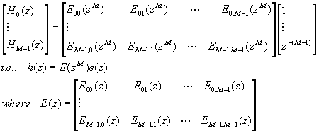
Another way to construct the PR filter banks is using polyphase decomposition. We can
express Hk(z) in the form:![]() , then rewrite this H array
as:
, then rewrite this H array
as:

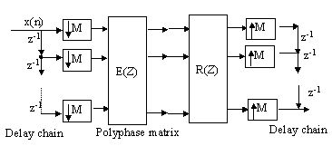
is the M´ M type 1 polyphase component matrix for the analysis bank. The left part of the following figure shows the idea pictorially. The right part shows the case of synthesis banks

In an similar manner we can express the set of synthesis filters, i.e., by type 2 polyphase decomposition,
![]()
Express above equation using matrix notation we have

In terms of e(z) and synthesis-bank vector f(z), this becomes:
![]()
where matrix R(z) is type 2 polyphase matrix for the synthesis bank.
Now combine the two polyphase decomposition and using the noble identities to move the expanders and decimators, we get the following diagram:

Finally, we can combine the matrices and get a M´ M matrix
P(z) : ![]()
The necessary and sufficient condition for the perfect reconstruction (PR) is:

for some integer r with 0£ r£ M-1. And it holds whether the system is FIR or IIR.
One sufficient (but not necessary) PR solution for the above filter banks is we choose
E(z) to be paraunitary, i.e., ![]() and for some fixed constant
d. The paraunitary property implies.
and for some fixed constant
d. The paraunitary property implies. ![]() . So
if we choose R(z) as
. So
if we choose R(z) as ![]() for some c¹ 0, the PR condition can be satisfied. Neither c nor K is
fundamental but choice of a positive K serves to ensure that R(z) [hence Fk(z)]
is causal.
for some c¹ 0, the PR condition can be satisfied. Neither c nor K is
fundamental but choice of a positive K serves to ensure that R(z) [hence Fk(z)]
is causal.
The Paraunitary constrain enables us to construct synthesis filter banks easily from
the analysis banks. That is, ![]()
There are several important properties caused by paraunitary solutions:
![]()
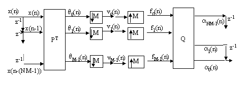
Orthonormal transform (including LOT, lapped OT) is a special case of filter banks. We may extract the delay elements of E(z) and R(z) to the delay chains and re-arrange the signal flow as:

where NM is the length of the filters of the bank. Actually this can be viewed as a transform with matrix PT, N=1 is the normal orthonormal transform, N=2 is the case for LOT.
We then define input vector, and partition it into N blocks of M samples each as follows:

The input vector is multiplied by PT to get the coefficient vector

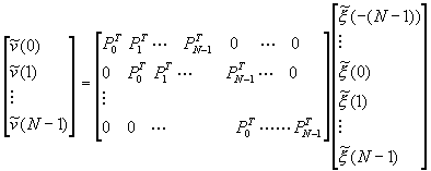
where each PkT is a M by M block. This can be written as
![]()
Because of subsampling (decimation) by M, every M new input samples are entered into the delay chain and then output v is calculated once.
![]()
Define ![]() , we then have
, we then have

This is like a block FIR filter, whereas the filter coefficients are the (M by M)
matrices and the signals are (M by 1) vectors ![]() . After N-1 samples
at the slow clock rate (i.e., (N-1)´ M original clock rate),
there is an entirely new data vector in the input delay chain (buffer). Stacking the
successive output, we get (starting at n=0 for convenience):
. After N-1 samples
at the slow clock rate (i.e., (N-1)´ M original clock rate),
there is an entirely new data vector in the input delay chain (buffer). Stacking the
successive output, we get (starting at n=0 for convenience):

To relate this representation to the filter bank structure, we can write

where the delay vector Z’MN is ![]() and
and ![]() , r=0,1,…,M-1
, r=0,1,…,M-1
This equivalence state that the block transform for x to q can be replaced by the analysis bank h, where the length of each filter is NM. Then we can obtain the polyphase representation of block transform, they have the following relationship:
![]()
now moving the decimator to the front of filter banks, we get:
![]()
Every element in matrix E(z) is a polynomial in Z-1 of degree N-1. Therefore we can express E(z) with matrix coefficients:
![]()
each Epk is a constant (no z-1 items), M´ M matrix and related with block transform with the following equation:
![]()
The synthesis (receiver) bank can be deducted in a similar way.