Fig. 1 | Fig. 2 | Fig. 3 | Fig. 4 | Fig. 5 | Fig. 6 | Fig. 7 | Fig. 8 | Fig. 9 | Fig. 10
Xing Zhou, Senior Member, IEEE, and Khee Yong Lim, Student Member, IEEE
Fig. 1 | Fig. 2 | Fig. 3 | Fig. 4 | Fig. 5 | Fig. 6 | Fig. 7 | Fig. 8 | Fig. 9 | Fig. 10
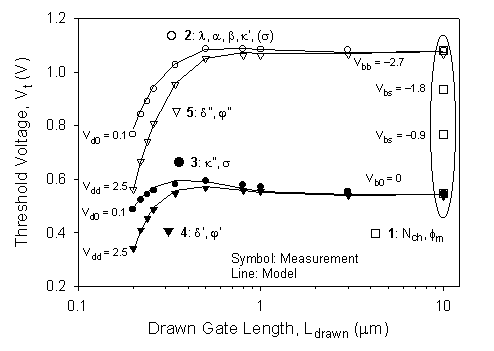
Fig. 1 Measured (symbols) and modeled (lines) Vt - Ldrawn curves at the indicated bias conditions showing the 5-step Vt and Leff parameter-extraction procedure.
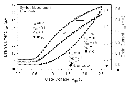
Fig. 2 Measured (symbols) and modeled (lines) Ids - Vgs characteristics at the indicated length and bias conditions showing the m0, Ab, and Rsd parameter-extraction procedure.
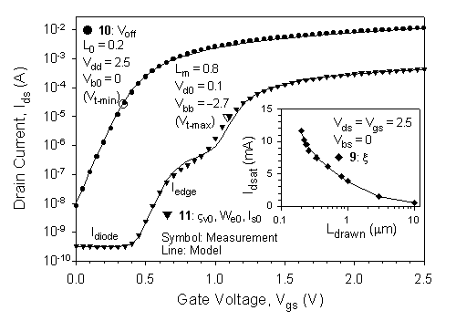
Fig. 3 Measured (symbols) and modeled (lines) Ids - Vgs characteristics at the indicated length and bias conditions (inset shows Idsat - Ldrawn) showing the VAeff, Voff, and Iedge parameter-extraction procedure.
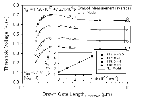
Fig. 4 Threshold voltage prediction of the model (lines) on the four wafers with different Vt-implant dose F shown by the average from 17 sites (symbols) through a simple correlation of the long-channel parameter Nch to F (inset).
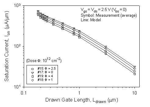
Fig. 5 Saturation current prediction of the model (lines) on the four wafers (symbols) in Fig. 4 using the same Vt - F correlation.
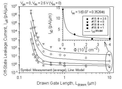
Fig. 6 Leakage current prediction of the model (lines) on the four wafers (symbols) in Fig. 4 using the same Vt - F empirical model together with a simple Is - F correlation (inset).
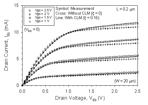
Fig. 7 Modeled Ids - Vds characteristics with (solid lines) or without (crosses) CLM for the 0.2-mm device compared to the measurement data (symbols).
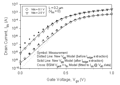
Fig. 8 Subthreshold log(Ids) - Vgs characteristics of the new Vgg model before (dotted lines) and after (solid lines) Iedge extraction, and compared with the BSIM Vgeff expression (crosses).
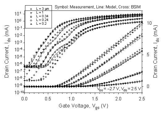
Fig. 9 Prediction of the length-dependent subthreshold and edge-leakage current (left axis) and turn-on current (right axis) of our one-region Ids model (lines) on the measurement data (symbols) for five devices, and compared to the BSIM3v3 prediction (crosses).
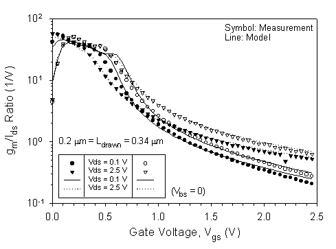
Fig. 10 Measured (symbols) and modeled (lines) gm/Ids
- Vgs characteristics in linear and saturation mode for two
devices.