X. Zhou, Member, IEEE, and W. Long
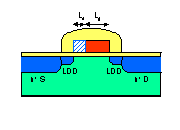
Fig. 1 Structure of the HMG-MOSFET.
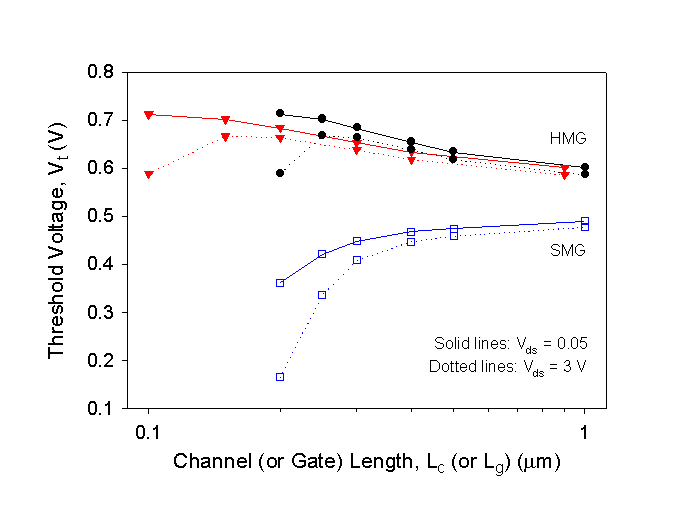
Fig. 2 Comparison of the linear (solid lines) and saturation (dotted lines) threshold voltages against channel length (circles) or gate length (triangles).
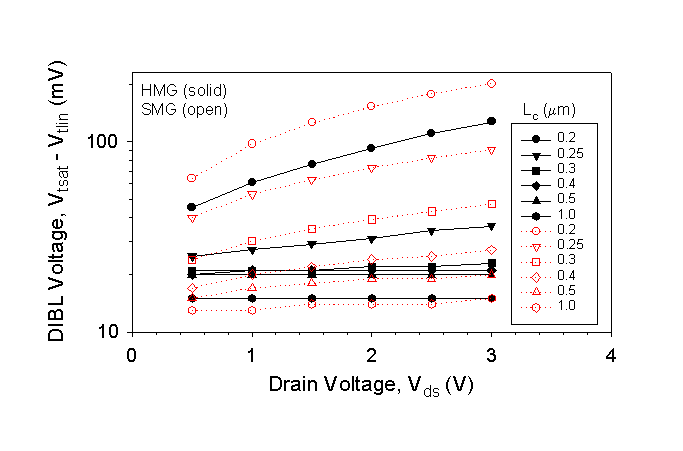
Fig. 3 Comparison of the DIBL voltages as a function of the drain bias for each channel length.
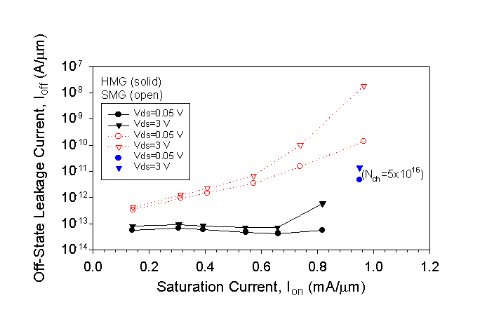
Fig. 4 The leakage currents (at Vds = 0.05 or 3 V) against the saturation current (each pair corresponds to a different channel length). One pair of Ion/Ioff for the HMG-MOSFET with Lg/Ls = 0.15/0.1 and channel doping Nch = 5x1016 cm3 is also shown as a comparison.
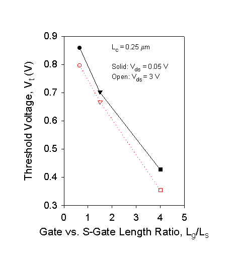
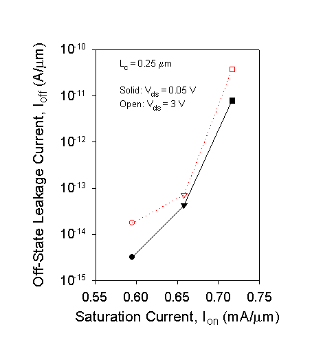
Fig. 5 (a) Threshold voltages as a function of the Lg/Ls
ratio, and (b) the corresponding leakage current vs. saturation current.
 (a)
(a)
 (b)
(b)