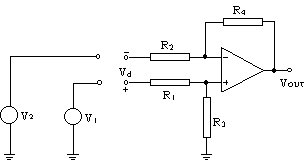
Gain of an amplifier is defined as VOUT/VIN. For the special case of a differential amplifier, the input VIN is the difference between its two input terminals, which is equal to (V1-V2) as shown in the following diagram.
So the gain of this differential amplifier is
Instead of applying superposition theorem with V1 and V2 separately, a better way is to first combined V1 and V2 in a different format, viz. (V1-V2). This is known as the differential mode input - Vd. Associated with this differential mode component will be the common mode input - Vcm., which is equal to the average value of V1 and V2.
Common mode component : Vcm = (V1+V2)/2
By using these alternate representation of the input components (Vd and Vcm) instead of the original components (V1 and V2), we can re-express eqn (2) in terms of Vd and Vcm as follows.
Since Vd = V1 - V2 ---- (4)
Substitute eqns (5) & (6) into eqn (2) :
VOUT = 1/2[R3/(R1+R3)] [(R4 + R2)/R2 + R4/R2] Vd +
= VOUT/Vd
= 1/2[R3/(R1+R3)] [(R4 + R2)/R2 + R4/R2]
Ad = 1/2[R3/(R1+R3)] [(R4 + R2)/R2 + R4/R2]
As there is another component in VOUT due to the common-mode component Vcm of the input, we define another gain for the differential amplifier, the Common Mode Gain (Acm=VOUT/ Vcm). From eqn (7), this is
To eliminate the effect of the common mode component, we can either
(i) make the input common mode component equal to zero,
i.e. make V2 = -V1
such that the average value of the two input signals equal to zero
or
(ii) can be achieved theoretically by making R1 = R2 and R3 = R4. However, this is not feasible in practice due to the tolerance of the resistors used.
Because of this imperfection, a figure of merit used to describe differential amplifier is the Common Mode Rejection Ratio (CMRR), which is defined as
CMRR = 20 log (Ad/Acm)
For a perfect differential amplifier, the CMRR is equal to ¥, as Acm is zero.
In practice, a CMRR in excess of 80dB to 100dB will be needed for high
accuracy measuring system (e.g. a microcomputer data acquisition system).
This is very difficult to achieve if the differential amplifier uses discrete
resistors for R1 to R4.