
XSAT On-Board Data Handling Subsystem
The OBDH subsystem comprises of:
- 2 X OBC (On-Board Computer)
- 1 X OIM (OBC Interface Module)
- 1 X SSR (Solid State Recorder)
- 4 X CAN (Controller Area Network) modules-residing in other subsystems
The functions of OBDH are:
- Receives, validates and processes ground commands; and execute or distribute these commands. These commands include those for parameters setting, code upload, TLE/time update, etc. as well as those for carrying out payloads’ mission operations
- Gathers, processes and formats housekeeping and mission data, and control downlink to ground. The OBDH will conduct autonomous housekeeping and health status monitoring operations and also store payloads’ operations data
- Supports attitude determination and control maneuvers of the spacecraft
- Supports safe-hold operations
OBDH Subsystem Connectivity
On-Board Computer (OBC)
The OBC provides the execution platform and environment for the flight software. This includes the processing capability and memory requirements for the Commands and Data Handling (CDH) software as well as the Attitude Determination and Control System (ADCS) software. The OBC is intended to be a reliable computing platform that will enable control of the satellite throughout the mission lifetime. Hence, components used on the OBC have been carefully selected to ensure survival and error free operation in the LEO environment.
Dual redundant OBCs are built into the OBDH for increased reliability. The two OBCs are cold redundant, thus only one OBC is operational at any point of time.
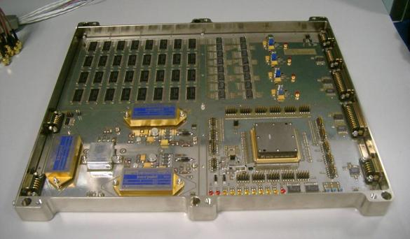
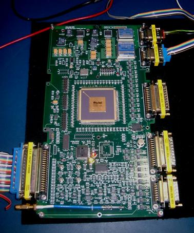
OBC hardware configuration
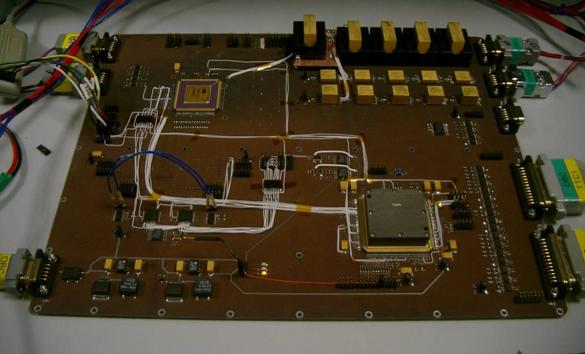
OBC QM Version 00 board
OBC Interface Module (OIM)
The OIM provides a link between the OBC(s) and a number of sub-systems and modules. The purpose is to reduce the input-output (IO) processing load on the OBC. The sub-systems/modules connected to the OIM include the PSS, GPS receivers, IRIS and SSR. In addition, the OIM distributes the 1PPS signal from the GPS receivers to the sub-systems/modules that require the 1PPS. These include the OBCs, IRIS and the Star Tracker. In the absence of the 1PPS signal from the GPS receivers, the OIM generates its own 1PPS signal based on its local clock.
The OIM is designed with two identical functional modules, named OIM1 and OIM2, within a same physical board. These identical blocks provide redundancy in terms of connectivity. This means that in normal operation, each OIMx will manage a different set of IOs. However, in the event that one of them fails, the other would be able to take over the IOs, even though the overall performance/throughput may be reduced. Each OIMx has on-board an 87C51RC microcontroller with 32KB on-chip EPROM for program memory and 32KB of external SRAM. In addition, there is an FPGA for implementing UARTs, digital IOs and the 1PPS functionality.
OIM QM board
Solid State Recorder (SSR)
The SSR is the high volume data storage module of the OBDH subsystem. It provides data storage and retrieval services to various sub-systems onboard X-SAT. It operates under complete control of the OBC (through OIM). The SSR aims to use commercial and hence low-cost memory modules for data storage and adopts a principle of reliability through redundancy. This sees the division of the total storage space into several banks of memory that can be powered-up and utilized by the controller unit on the SSR. The division of the storage space into independent banks allows the isolation of faults such as SEUs and latch-ups caused by environmental factors and prevent such faults from propagating throughout the module. The SSR also enhances the integrity of stored data through the use of an Error Detection and Correction (EDAC) scheme. The SSR does not contain any microcontroller/processors. Instead, a FPGA is used to implement all the required functionality.
The SSR provides a differential UART link to the OIM module from which it receives all its operating commands and scenarios. This link is also utilized for the low speed transfer of stored payload data to the ground as well as some ground upload data consisting of application codes for other sub-systems. The SSR provides high speed differential LVDS links to the XBT subsystem and IRIS and PPU payloads. These links are primarily used for the transfer of image data.
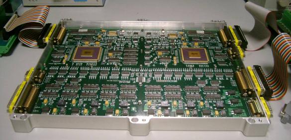
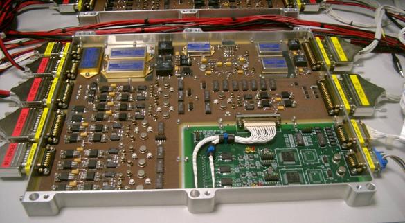
SSR hardware configuration
SSR QM Version 00 board
The CAN modules provides the respective subsystems an interface to the dual redundant CAN bus, allowing for transferring of telemetries and telecommands between the OBC/OIM and the subsystems. The electrical commands to be delivered to and from each subsystem are varied in complexity, format and interconnectivity. The CAN bus and the CAN modules provide a single electrical means of linking the OBC to the subsystems with minimal point to point links together with the flexibility of communicating to them through custom designed signal interfaces. A total of 4 CAN modules form part of the OBDH subsystem. However, physically, these modules reside in the trays for the respective subsystems. The 4 CAN modules are: PSS-CAN, XBT-CAN, TTC-CAN and PPU-CAN.
The basic design of the CAN module is similar; the differences are in the IO interfaces. Each CAN module consists of:
CAN hardware architecture
PSS-CAN residing in PSS-PDM2 (QM)
TTC-CAN in TTC-CCSDS (QM)